Home > Archive > Blair Bridges > Bridge Rebuilt
Missouri River Bridge at Blair, Neb., Rebuilt
By O. F. Dalstrorn
Bridge Engineer, Chicago & North Western. Chicago
From Railway Age 11-22-24 Vol. 77, No 21. 931-934
Abstract of a paper present before the Western Society of Engineers Chicago, on November 17.
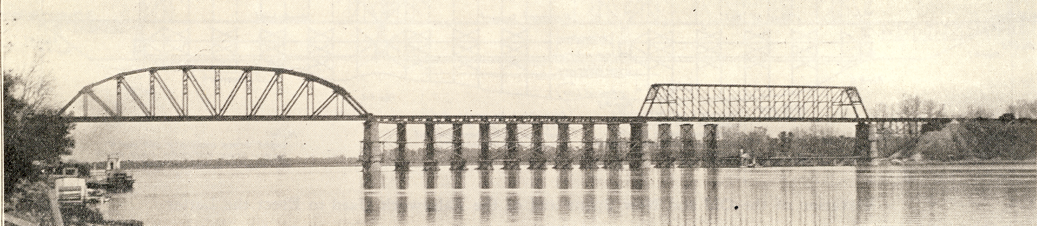
In 1923 THE CHICAGO & NORTH WESTERN reconstructed its bridge over the Missouri river near Blair, Neb. This bridge was built in 1882-83. The superstructure, designed for the small engines and light cars of that day, was not strong enough for present day loads. The substructure, however, was of adequate strength. The four river piers were used in the reconstructed bridge without any remodeling to carry the new spans, while the piers and abutments of the approaches were remodeled to receive the new approach spans, which differed in type and detail from the old spans. The old bridge provided originally for three 330-ft. through truss spans over the river channel, with approaches consisting of one 110-ft. deck truss span and one 22-ft. 6-in. deck plate girder span at each shore. The 110-ft. truss span in the west approach was replaced with a 176-ft. truss span after the bridge was completed. The total width of waterway provided for in the design was about 1,000 ft. The clear head room was 50 ft. above mean high water. The width of waterway necessary was determined by the width of the river at points some miles down stream from the proposed site, where the river, confined by banks on both sides, was somewhat less than 1,000 ft. wide, the waterway being clearly sufficient for the river at flood stage. The clear head room under the bridge was established by government engineers to provide adequate clearance for existing and for contemplated river traffic.
The Substructure Was in Good Condition
The substructure for the three 330-ft. river spans consists of four masonry piers on caissons sunk to rock. The piers under the shore ends of the 110-f t. approach spans were concrete-filled steel cylinders on pile foundations. The 22-ft. 6-in. girder spans at the extreme ends of the bridge extended shoreward from the cylinder piers, their shore ends resting on masonry abutments buried in the embankment. The purpose of the short girder spans was to fix the end of each embankment far enough back from the cylinder pier to bring the slope below the tops of the cylinders.
The stone for the piers was quarried at Mankato, Minn., and is an excellent grade of limestone, originally of a yellow color. The cutwaters of the upstream ends of Piers 4 and 5 were of blue granite, quarried at St. Cloud, Minn. The face stones were laid in Portland cement mortar. The backing was laid in Milwaukee cement mortar, except that laid during freezing weather when Portland cement was used throughout. The specifications for the masonry were very exacting as to quality of materials and workmanship.
When the reconstruction of the bridge was proposed, an inspection of the piers was made to determine whether their condition and probable length of life would justify erecting the proposed new superstructure on them. Every face stone in the four piers, above water level, was inspected. This inspection showed two kinds of weathering effects; some stones were pitted all over 1/4-in. to 3/4-in. deep and were rough to the touch, as if some soluble ingredient had been dissolved out. The other stones were wholly free from pitting, but many of them were spalling slightly. Fresh surfaces where spalls had dropped away recently and a few spalls still clinging to the stones, showed that the spalling was still going on. The loss by spalling or pitting, however, was so small that it was hardly appreciable except in one stone on the west side of Pier 3, near low water level, which had spilled off to a depth of nearly six inches over its entire face. This stone has since been faced with concrete.
The mortar in the joints was in excellent condition, no evidence of deterioration being found. The piers have never been pointed since they were built. Small dabs of mortar spilled on the lower courses during construction had hardened on the stones and could be dislodged only by a sharp blow with a hammer.
A number of cracked stones were found on this inspection. There were also a few cracks at joints. All except two cracks in the stones were vertical, generally near the middle of the stone and extended through only one stone. Two of the cracks were horizontal, one of them in a stone that showed signs of lamination. The largest cracks would barely admit the point of a knife blade, while the smallest were hardly more than visible. All of them appeared to be old cracks. The vertical cracks were probably caused by uneven bedding of the stones when laid, the stones cracking in vertical planes under the action of the superimposed load. The cracking permitted the stones to adjust themselves to the uneven bedding and no further developments followed. On the east side of Pier 6, near the north end, is a joint crack running through five courses and through the connecting segments of the horizontal joints. There was no evidence of displacement of the stones, the crack being only about 1/16-in. wide. From the records of the inspection it was estimated that the piers were still good for not less than 50 years and probably much longer.
The piers under the shore ends of the 110-ft. approach spans consisted originally of two concrete-filled cylinders in each pier, built on pile foundations. The cylinders were 5 ft. in diameter, 12 ft. apart center to center, and connected by steel bracing from top to bottom. The shells were of 5/16 in. metal. The cylinders for the west pier were 42 ft. 9 in. long; for the east pier they were 13 ft. longer than those of the west pier, on account of the lower level of the ground line at the east pier.
In 1900 it became necessary to remodel the two-cylinder pier in the east approach, making it a four-cylinder pier with bolsters on top, on account of a slow westward movement of the east embankment. No change in the superstructure was necessary. When the bridge was reconstructed in 1923, the pier was remodeled by cutting down the cylinders and lowering the bolsters.
On account of disturbances in the west embankment in 1884, it was decided that the end of that embankment should be kept farther away from Pier 6. Accordingly the 110-ft. span was taken out in 1885 and replaced with a new span 176 ft. long, the shore end resting on a concrete and I-beam grillage, 12 ft. by 24 ft. by 6 ft., buried in the embankment, which was sloped back to conform to the outline of the new span. The 22-ft. 6-in. girder span was re-erected at the end of the new span. The upper portion of the old cylinder pier was removed to a level slightly below the surface of the new slope.
In the reconstruction of the west approach in 1923 the 176-ft. deck truss span was replaced by two deck plate girder spans and a steel bent. The substructure for the steel bent consisted of two separate concrete pedestals built on concrete foundation piles about 40 ft. long. These pedestals were placed 23 ft. 6 in. apart to permit a pile driver to work from the track with leads suspended outside the bridge, the vertical clearance below the span being too small for a pile driver. This accounts for the width of the bent at its base, which is considerably more than required for stability.
The old concrete and I-beam grillage at the end of the truss span and the old abutment were remodeled at the bridge seats to fit the new girder spans. The new approach spans were so designed as to require but little remodeling of the substructure.
In the reconstruction of the east approach the old 110-ft. deck truss span was replaced with a deck plate girder span of corresponding length. The old cylinder pier was cut down, the I-beam grillages replaced at the lower level and a transverse bolster built of I-beams set on the grillages to carry the girder span. To carry the end of the deck truss span while the pier was being cut down and remodeled, a special steel bent was built and set in place under the bearings.
Approaches Were on Unstable Foundations
The approaches at both ends of the bridge originally consisted of timber trestles on one per cent grades. The trestle at the west end was not contemplated in the original plan, which provided that this embankment should be finished to grade while the bridge was being built. When this embankment had been brought up to grade to within about 300 ft. of the west end of the bridge as established, a settlement of about 6 ft. occurred during the night of July 19, 1883. The ground at the sides of the embankment rose about 6 ft. at the same time. Borings revealed a layer of soft mud below the top layer of hard material, evidently marking the course of an old channel. The filling was continued until the embankment was again brought to grade; settling continued during the progress of filling, the ground at the sides rising about 14 ft. before equilibrium was established. It was estimated that the total settlement of the embankment was over 40 ft.
The embankment adjacent to the bridge was not carried up to grade at this time. The east end was leveled off at the full width of the finished embankment about 35 ft. below the level of track on the bridge, and a trestle about 220 ft. long was built to carry, traffic until the embankment could be finished. The embankment was finished to grade up to the end of the bridge in 1884, but almost immediately after completion a section adjacent to the bridge settled about 10 ft., carrying the cylinder pier down with it. The span carried by the cylinder pier was held to grade during the settlement by blocking laid up as the settlement progressed. This settlement was near enough to Pier 6 to produce a slight movement, the top of the pier being displaced about 9 in. toward the river. It was not believed that the pier had been cracked or otherwise damaged, the displacement being accounted for o by compression in the timber cribwork in the lower part of the pier. There has been no disturbance or unusual settlement of the embankment since 1884, and no further displacement of Pier 6 since that date. It was on account of these disturbances that the 110-ft. span was replaced in 1885 by the 176-ft. span previously mentioned.
The history of the east approach is quite different from that of the west approach. Since the material for filling had to come from the cut on the west side of the river, this embankment could not be constructed until after the bridge should be completed. Accordingly a timber trestle 3,000 ft. long was built to carry traffic temporarily. Filling was begun in the winter of 1883-84 at the end farthest from the bridge. In March, 1884, the highwater carried away 1,600 ft. of the trestle adjacent to the bridge, being all of the trestle not protected by the filling. The trestle was rebuilt at once. Filling was continued during 1884, the portion not disturbed by the March high water being filled to grade and the filling well started under the rebuilt portion that year. The entire embankment was completed in 1885.
No settlement occurred during the filling of the east approach such as those that disturbed the west approach. However, a very slow westward movement of the cylinder piers following the completion of the embankment showed that the end of the embankment was moving toward the river. There was also a slight vertical settlement of the cylinders, as would be expected. The records do not show when this movement was first noticed, but it probably began before the embankment was actually completed. As the pier carried the fixed end of the deck truss span, this span was carried westward with the cylinders and embankment. When the movement had carried the deck span westward a few inches it became necessary to shift the pedestals on the cylinders eastward, drawing the span back to its original position to prevent it from crowding against the east river span. By 1900 the top of the cylinder pier had moved toward the river about 10 1/2 in. and was still moving. The end bearing of the span had by this time been shifted toward the east side of the pier as far as it could go. The west end of the span was crowding against the end of the adjacent river span, making it necessary to repeat the shifting of the deck span. To remedy this condition and provide for future movement of the pier, a pair of cylinders, similar to those in the original pier but only 35 ft. long, were set 8 ft. 5 in. back of the old cylinders and filled with concrete. The old cylinders were cut down about 1 ft. and two I-beam grillages filled with concrete were set on top of the old and the new cylinders, parallel to the axis of the bridge, forming bolsters for carrying the truss bearings.
When the cylinder pier had been remodeled the deck span was moved back to its normal position. Also at this time the fixed and expansion bearings of the span were interchanged, the expansion bearing being transferred to the cylinder pier so that any further displacement of this pier would take place without displacement of the span. The slow movement of the pier continued after the new cylinders had been put in, all of the cylinders moving with the embankment. By 1920 they had moved so far that the base castings under the bearing rollers were almost in contact with the diagonal truss members. This was corrected in 1921 by sliding the base castings back a few inches and anchoring at a new place on the bolsters.
In 1921 a quantity of heavy stone from the abutments of an old bridge near Missouri Valley was put in along the foot of the slope where it projects into the river, the outer layer being stones of boulder size. These large stones, being massive enough to withstand the ice and the current at high-water, have protected the embankment against scour and no further displacement of the pier has been observed since this was done. The total displacement of the top of the old cylinders from their original position is 21 in.
Superstructure Showed Little Deterioration
The entire superstructure was in excellent condition when taken down. No reinforcing and very little repair work had been done on any of the spans during their forty years of service. In 1900 the short sections of eye bars in the adjustable counters in all three river spans were replaced with new pieces, on account of defects that developed in the original bars. In 1920 the connection angles in a number of stringers of the river spans were found to be cracked in the fillets and were replaced with new angles-12 pairs in all. In the same year several floor beams in the 110-ft. and 176-ft. approach spans were repaired where they had developed cracks in the webs near the bottom of the stringer connections, evidently due to the thrust from the ends of the bottom flanges of the stringers. In 1923 some cracked connection angles of stringers in the deck truss spans were on the order to be replaced, but the spans were taken out before it was necessary to do the work. The cause of these failures in the floor member details, at this late date, was probably the heavy cars which by 1920 were more severe on the floor members than the locomotives. There had been no increase in the weight of locomotives over the bridge for about 20 years.
There was no evidence of deterioration of the structure when taken down. There were no shoulders on the pins and no elongated pin holes. A number of the pins stuck fast in the top chords and the posts. Those in the chord that could not be loosened were burned off. Those in the posts were left there, the eye bars being simply slipped over the ends of the pins.
The history of this bridge is a good demonstration of the endurance of such a structure under favorable conditions of service and maintenance. It represented the best class of material and workmanship of its day. Traffic was always comparatively light, only a few trains a day each way. Situated at the summit of long, heavy approach grades, it was never subjected to the high speed of trains, which could scarcely attain the speed limit of 10 miles per hour allowed. Loading was always well within the capacity of the bridge until recent years when trains of heavy cars probably produced stresses in light truss members above the limits allowed in good practice. Rigid inspection was maintained by the general bridge inspector and the division inspectors. After forty years of service, there were no indications from which to determine the limit of life of the structure under existing conditions. It looked good for 40 or 50 years more of the same kind of service, and gave no means of fixing the limit, since there was no measurable deterioration.
The three river spans were taken down in shape for re-erection. One of these has been assigned for re-erection over the Wind river near Riverton, Wyo., while the other two spans are stored at Blair. The deck spans were taken down as scrap, their size and shape making it impracticable to find a place to use them.
The New Superstructure
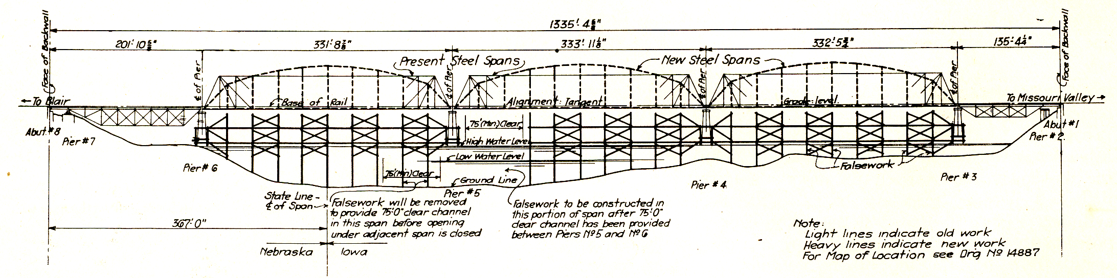
The new superstructure was designed for Cooper’s Class E-60 loading. It was designed and built under the American Railway Engineering Association specifications for steel railway bridges, edition of 1923. The new spans were fitted to the four old river piers without any remodeling of the piers. In order to make the three river spans alike it was necessary to load Pier 6 eccentrically. The center line of truss bearings is 6 in. west of the center line of pier, and the center line of girder bearings is 2 ft. 11 in west of the center line of pier. This eccentricity of loading was due to the displacement of Pier 6 toward the river as already indicated. As the pier was of ample strength for the new loading, and as the eccentricity of loading was in the direction opposite to the displacement of the pier, it was considered of too little importance to justify a special length of span to fit this pier.
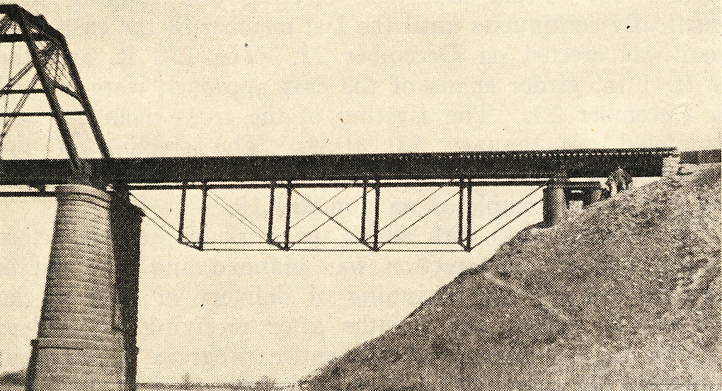
The old deck truss spans of the approaches were replaced with deck plate girder spans and the substructure remodeled accordingly. The 176-ft. span of the west approach was replaced by two short girder spans and a steel bent, a more economical type than the single long span.
The new superstructure was designed by the American Bridge Company and fabricated at its Gary plant. The contract for the erection of the new superstructure was also awarded to the American Bridge Company. This contract, which was distinct from the contract for design and fabrication, included the construction and the removal of the falsework, the removal of the old superstructure and the erection of the new. The railway company furnished all the piles and lumber for the falsework, but none of the framing iron or the steel I-beams for the falsework deck. The contractor was required to take down the three river spans without damage to the members, so that these spans could be re-erected elsewhere. The approach spans were to be taken down and loaded in convenient way, except that stringers were not to be damaged, and were to be loaded separately in cars. These stringers were of a size and length making them good material to keep on hand for ordinary falsework.
A convenient storage yard was available on the west bank of the river just north of the bridge.
The Erection Proceeded Rapidly
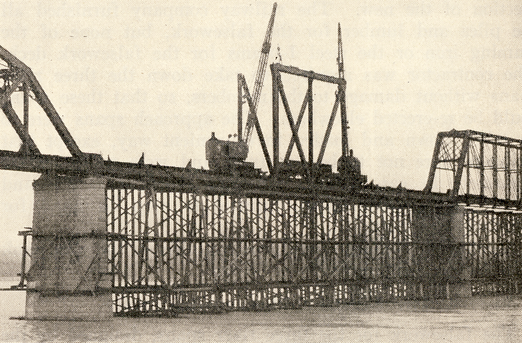
The falsework for the three river spans, designed by the American Bridge Company, consisted of framed bents on piles. On the bents were set the I-beams, 24 in. by 115 lb. by 36 ft. which carried the traffic and the structures during the removal of the old and the erection of the new bridge. The piles furnished were Oregon fir, 70 ft. long, very large and straight. In approving the falsework plan, the railway company changed the longitudinal and transverse braces from nominal small sizes to 12-in. by 12-in. and 8-in. by 16-in., in order to secure good bridge timber from the salvage. This extra-heavy bracing rendered good service later when a sudden rise of the river threatened to destroy the false-work in the west channel spans.
No falsework was provided for the erection of the approach spans. The 176-ft. truss span in the west approach was shifted northward 19 ft. and landed on temporary pile piers, and the new spans and bent erected with cranes working from both levels. Traffic was suspended about ten hours while this change was being made. The old truss span in the east approach was cut up in place with Oxweld, outfits and loaded direct into cars. The new deck girder span was erected by using two locomotive cranes, one at each end, to set the girders in place. Traffic was suspended 6 1/2 hours for this operation.
There were only two periods of suspension of traffic in, the entire program of erection. Some interruptions to train movement occurred when it was necessary to hold trains until the locomotive cranes could let go of the work in hand to move off the bridge and get in the clear.
The erection of steel in the west river span was begun October 13. From that date erecting and riveting were practically continuous until the last member of the east river span was erected on December 22. The 110 ft. and the 22 ft. 1 in. girder spans of the east approach were erected on December 19. The riveting of the truss members was completed on January 15, 1924. The erection of the brackets for planking and handrailing followed the other work and was completed on January 19.
The thoroughness with which the work of the contractors for fabrication and erection was planned and executed is demonstrated by the beginning of delivery of steel at the bridge site within five months after receiving the order; and by the completion of the entire program of erection, including the construction of the falsework and its removal, in a little more than six months.
Deck and Track
Ample provision is made for the protection of the deck and bridge against damage by derailments. The steel guard angles and 4-in. by 8-in. guard planks protect the ties against damage by ordinary derailments. The 10-in. by 12-in. guard rails, notched over the ends of the ties and bolted to every tie, hold the ties against bunching by derailed trucks, and prevent derailed cars from drifting into the trusses.
The free movement of the rails and expansion ends of spans, independent of each other, is provided for in five expansion joints in the rails, conforming in position to the expansion ends of the spans. An expansion joint in the rails at each end of the bridge protects it against damage from movement of the rails in the track beyond the ends of the bridge. The deck, track and railing were placed by railway company forces. The total weight of the spans aggregated 5,122,379 lb.
Adjust the text size


Featured Pictures
Archive Links
BHPA Links
Blair Historic Preservation Alliance | P.O. Box 94 | Blair, Nebraska 68008 | contact@blairhistory.com